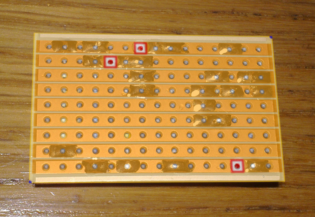
The build I'm using in this guide for simplicity is an NPN silicon Fuzz Face I built a while ago:

and yes I know this one wouldn't work without transistors! :o)
1) Transistor Orientation
With my earlier layouts (hopefully not so many recently) I used the transistor symbol purely as a graphical representation of a transistor. I always included the required pinouts but often people have taken the orientation as correct (understandably unless you've known what I've written about it in the past) and so if you're having problems with a transistor build (especially from an older layout) then first thing to do is check the datasheet for your own transistors to make sure the orientation matches. I always socket transistors to allow me to experiment with different types and gains and would always suggest everyone else do the same. You can use PCB header sockets (found on eBay) which cost me £5.55 for 20 strips of 40, which is enough to socket 266 transistors. Not a lot of money to allow you to experiment easily with every build. As a bonus it's also easy to turn a transistor round if the orientation is wrong.

2) Faulty components
This is really something to check before a build. Once the components are in circuit you can't guarantee they will measure accurately and as you can get a cheap multimeter that can measure both resistors and caps for not a lot of cash, then everyone should be doing this first. I've done a number of builds where I was tearing my hair out and as I destroyed the board in anger, measured components afterwards, usually to find a faulty electrolytic cap. If you have the patience then do it because it can save you a lot of heartache. If you don't have the patience, then develop some! :o)
3) Cold solder joints
If you're getting noise (or no sound at all) from your build, then a good thing to check is for cold solder joints.

You want all soldering to be shiny and so look out for dull looking points or pitted solder, and reflow if necessary to make sure you've got a strong connection.
4) Unwanted Bridges
When you make a track cut in vero you always run the risk of leaving a burr that is making an unwanted bridge across tracks which will almost certainly stop the build from working properly. Similarly solder can stray sometimes to cross the groove between strips and cause the same problem.
If you've got a multimeter the best way to test this is to use the audible diode test to check for continuity between consecutive tracks including points in the row which have been isolated by track cuts. So in the Fuzz Face example this is where you would want to look for continuity.

If an unwanted bridge is found then use a sharp knife to cut between the tracks and break the bridge. It may be worth using a magnifying glass to make sure nothing is left which could cause additional problems in the future.
If you don't have a multimeter then just score between all the tracks with a sharp knife, or better still a small hacksaw, to make sure there is complete separation.

5) Checking placement and cuts
I often come across problems with builds where a part was soldered to the wrong hole, or a cut misplaced and again in most cases this would stop the effect working. With smaller layouts it's easy enough to go over everything and double check but I use a visual method to help me check for placement errors. Anyone who uses a graphics editing program like Photoshop or Paint Shop Pro should be able to do this easily enough, but not everyone wants to mess around with graphics programs to fault find a build, and if that is the case then just check your placements critically against the layout, counting holes to make sure everything is where it is intended to be. You can ignore the rest of this section and skip to number 6.
I take a front and back pic of the board and then use the layout pic to create a semi transparent layer over the top. For the top of the board just select right round the board layout and copy and paste it as a new layer over the top of the front photo. Then you can make it semi transparent by setting the layer opacity. Then use a deformation tool to line up the layout with the photo (it's easiest to try to lineup the vero holes as points of reference). The results make it very clear where everything should go and highlight errors

Do the same with the reverse side (don't forget to mirror the layout before pasting over the picture so it's the correct way round.
Using a filter on the track side can make it more obvious where the photo and layout cuts are. This was using a simple "Darken" blend mode

6) Measurements
If the above all looks good then we need something else to give us a clue to where your problem arises. The best way to provide this is to measure the DC voltage between all transistors, ICs, regulators etc and ground. Any voltage that isn't in the right sort of ball park will stand out like a sore thumb, so if you want help make sure you do this first to give us something to work with.
To assist you in giving us the correct information, ICs follow the following numbering convention:
1----8
2----7
3----6
4----5
and if the circuit contains transistors be sure to identify collector, base and emitter when giving voltages.
7) If all else fails .....
If all of the above check out ok, then the problem must be an incompetent layout designer! :o) In this case post a message to the board including any front and back pics you've taken, along with the pin voltages mentioned in (6) and that could really help identify the problem area.
Hopefully you have more successes from this blog than failures to make the frustrations worthwhile.
Hi
ReplyDeleteUseful guide.I´m having problems with troubleshooting my Woolly Mammoth build.I did all of the above except checking capacitors.I have a multimeter but it is´nt capable of measuring capitance...Is there a way to check capacitors without having to buy a new meter??
Thx :-)
http://www.youtube.com/watch?v=ttzqpTWDDAc
DeleteOr just get one of these:
http://www.ebay.co.uk/itm/260841152985
They're really good. I've got the model that this one replaced and it measures pf values much more accurately, and uF values much more quickly than a much more expensive meter that I've got.
Ok cool.New import tax-laws for non-EU countries will charge me an insane amount of money for any purchase over 9£ so i´ll have to look for something within the EU.I suppose one could go all the way and get an Atlas ESR but how about this one:
ReplyDeletehttp://www.ebay.co.uk/itm/LCR-RCL-INDUCTANCE-CAPACITANCE-RESISTANCE-METER-W-Leads-/260838255647?pt=UK_BOI_Electrical_Test_Measurement_Equipment_ET&hash=item3cbb2bec1f
Will it be able to do the same?
I've honestly no idea, I've never seen or used that model. Are you in the UK? If so, you don't get charged duty unless the transaction would incur duty of at least £9, not a purchase over £9. I buy from China, Thailand, Malaysia, the US, in fact just about everywhere all the time, and I've only been charged duty once ever. And that was about £70 order of resistors coming from the US. I frequently place £30-£40 orders with China and never had any charge.
DeleteNo i´m in Denmark.Any purchase over 9 £´s will set me back an additional 25-30 £´s for import tax + "Handling"...>:-(.(No more Tayda orders for me).
DeleteThat's ridiculous. Governments create smugglers by imposing this sort of draconian restriction. Still you could always get orders shipped to someone you know elsewhere in the EU first who could then forward them on. You'd have to pay shipping from the them to Denmark but it'd be a lot cheaper than that sort of duty.
DeleteHej Martin Hvorfor handler du ikke i Tyskland...Musikding og Banzai har det meste...Det er helt normalt med moms + Told mm. hvis du handler uden for Eu.
DeleteSorry Folk´s This was in Danish..
Hilsen fra Ole Staalhaar København
Hey Ole.Yes i use Banzai,Musikding etc...But some things you can´t get from within the EU...And some low price shops like Tayda in Asia are just off limits for us danes.
DeleteYes it is absolutely ridiculous!.They keep changing the laws.It used to be 40 £ value before you should pay tax...And now it´s a mere 9 £´s.I´m ok with paying the "Moms"-tax of 25% of the value but their "Handling"-charges are the kind of stuff that makes you see red.They will charge you 20 £ for nothing.
ReplyDeleteI guess one could do it like you describe or if i make very large orders it could still be cost effective...Problem is my economy can´t handle spending 100´s of £´s at one time.
Customs is currently holding on to a box of PETP capacitors i got from Ukraine.I paid like 15 £´s for it but with tax and "handling" they could end up being very expensive capacitors :-o
Things like that make me angry. Don't mess with a man's capacitors!! :o)
DeleteI order a lot from the far east, but my orders mostly tend to be under £10 and only go over that when I'm ordering something a bit more special like a quantity of stomp switches or PCBs. I've noticed that most sellers that I buy from in the far east tend to put $10 for the value every time, nice that they're helping to stop us getting ripped off by our respective governments!
Oh and try KW-TUBES for those PETPs. He's in Lithuania so you won't get taxed.
Customs? Isn't that what they Krays specialized in back in the mob days?? F@*king Governments! 'Free market' my arse!
DeleteI notice the same Mark, the seller I get my switches from, labels them as a 'gift' lol... I keep my orders small but frequent.
Yeah i got some stuff from him.Unfortunatly he did´nt have the value i was looking for this time...And he does´nt have germanium transistors.I have built a couple of fuzzes using russian GT´s.They turned out quite nice...In fact surprisingly good!:-)
ReplyDeleteSpeaking of capacitors:Polypropylene,metallised poly,mylar etc.Is there a thumbrule of where one type is better to use in a circuit than the other?.Sonic caracteristics etc.?
I've tried posting this question in other places but am having no luck.
ReplyDeleteHere goes. I've got a circuit that has 2 outputs. I need each output to be volume controlled and they both need to be sent to one audio out jack. The .jpg shows the layout I just wired up. The problem is that they are not independent; they are interfering with each other. How do I need to change this layout to make it work. Thanks for any help.
http://i1270.photobucket.com/albums/jj611/the_8lack_hat/JlAB/Q1_zpsa4724840.jpg
I've been recently battling with a similar issue. http://www.beavisaudio.com/techpages/Pots/PassiveMixer.gif
DeleteThat could solve it. Didn't solve it in my case, because the two signals were just too different..
+m
I will pop that on the breadboard tonight; it looks as if it may work for me. Thanks m
DeleteWhat have I done wrong, since the pedal I just finished (Tremulator), is producing hum/static noise, especially when I don't touch the strings? Is it a ground problem?
ReplyDeleteHelp is highly appreciated! :)
Sounds like one. Just yesterday i put that same layout together with no issues or any noise. Actually, noisewise it is quiet as a lamb. Do you have both jacks grounded? Did you use Mark's offboard wiring guide (http://tagboardeffects.blogspot.fi/2012/02/offboard-wiring.html)? Could it be just a bad joint at some ground connection?
DeleteThose would be my first guesses...
+m
I have made my own wiring guide, it's here: www.turntable.dk/diy/Wiring.jpg
DeleteJust ignore my remarks on it : )
/C
Nice one, I'll point people towards that when they ask about batteries
DeleteThat looks great. So there can't be an issue with the wiring itself. Bad joint woould be a likely suspect...
Delete+m
Ivlark@ I have put up a new wiring guide (in english). You are welcome to put it on your site, but it's very inspired by a guide from GuitarPCB - I hope they won't sue you then! ;o)
Delete@Mirosol Thanks, I'll check all connections :o)
Is it possible to remove crackle from the pots ?
ReplyDeleteIt depends what the effect is, some pots are meant to crackle
DeleteI have built Death by Audio Supersonic Fuzz Gun . Bias pot and Fuzz Pot Crackle . I have also built Lovepedal
ReplyDeleteenglish gent and gain pot also crackles . Is it possible to remove it ? I think original effects don`t crackle .
I have a build (not in enclosure yet) that only produces a loud buzz UNNLESS i touch the metal on both the input & output jacks, then the effect works...Do you think this will work once it has all been mounted in the enclosure?
ReplyDeleteHave you grounded the input and output sleeves?
DeleteI think I fixed it. I had 2 seperate wires going to both +'s on the DC jack. I put them both to the same one and it's working now.
ReplyDeleteAlthough, I think the Belton brick was labeled wrong...It's supposed to be the long decay and it seems short. Is it possible that one of the components is shortening the verb?
i'm having some trouble with just about all my builds! i'm a novice, so that probably accounts for a lot -- but anyways, i've checked and everything seems to be in the correct spots...but i'm getting TONS of noise (like radio stations, etc) sometimes even when the pedal isn't engaged! any help would be awesome!
ReplyDeleteThe box should help a lot with RF noise, are you sure it's properly grounded? It may be that you just have a noisy supply in which case a power filtering extension could help.
DeleteA couple of things you can do with any circuit may also help, firstly put a low value resistor like 100 ohms in series with the cupply to the board, and you could also put a low value cap like 47pf from the input wire to ground. Both of those help with RF.
Hi,
ReplyDeleteSome of the pedals I've built lately have no problem with my power supply at home but, as soon as I use them somewhere else, I can here a costant noise (possibly ground noise).
How could I fix that?
Some places just have noisy mains, but the fact that they're quiet at yours shows that the pedal itself isn't at fault. To try to combat supply noise it may be worth getting one of the mains adapters for your gear that has built in power filtering which may help.
DeleteThanks!
ReplyDeleteThe problem is that I've built some pedals for friends and they use different power supplies.
I Built the little angel chorus pedal on this site and I get my bypass sound fine but when i engage the effect I get silence, I've check everything suggest above except I don't have a multimeter. Is there any ideas to what it could be suggest I would really appreciate the help.
ReplyDeleteI have built 2 successful pedals with builds from this site, and the last 2 have the EXACT same problem which is frustrating me like crazy; with power hooked up and nothing plugged into the input jack, I have a very faint LED light on but no tone. When I plug something into the input jack, the LED light turns off. Bypassed works as expected, engaged I get nothing. I'm doing the same thing I did with my first 2 builds (for offboard) and I'm at a loss. Any feedback?
ReplyDeleteI should add that I'm using the offboard wiring layout from Beavis Audio (http://www.beavisaudio.com/techpages/StompboxWiring/StompboxWiring.gif)
DeleteHi, I recently finished my first build, when I plug in I get a very loud static sound and nothing else, I think my board is fine, the problem is that I couldn't get ahold of a footswitch with nine points on it, mine has six. (I live in South Africa) So I tried to re-design the off board wiring, I am pretty sure that is my problem. Is there a correct way to do this? Is it even possible ?
ReplyDeleteMy number is 082 5516 525. I am in Centurion.
DeleteThis comment has been removed by the author.
ReplyDeleteI just put together the lotus pedals snowjob underdrive. The sound is going through, but only if the drive and volume are all the way up. it almost kind of muffles the tone. But it doesnt seem to be doing the job right either way. Help would be appreciated!
ReplyDeleteThis comment has been removed by the author.
ReplyDeleteHey, I have quite a problem... I built a mini Chorus from a kit (not from this site, but I hope to find someone here who can maybe help me) and the weird thing about it is, sometimes it does work and sometimes it doesn't... I have no Idea what could cause this problem!! When it doesn't work, the LED still glows, there's dry sound, but no effect. Also the Footswitch makes quite a popping noise which doesn't occur when the pedal is working fine (which it really does from time to time!) so how is that possible? I am sure that the circuit is built correctly, I've checked it at least 5 times. it just drives me crazy!
ReplyDeleteThe pedal usually starts working after I disconnect the power supply (Boss PSA adaptor) and put it on battery for a few seconds and then swap back to the normal power supply... But even that's not always the case...
DeleteDoes anyone have an idea if this hints some sort of (occasionally?) faulty component?
This comment has been removed by the author.
ReplyDeleteHey Sandy, what sort of power supply are you using? If you have a crappy DC adapter, they are sometimes noisy and ruin everything. Try it with a battery and see if you have the same results.
DeleteThis comment has been removed by the author.
DeleteOops, my bad - had the test pedal sitting on top of my amp and the noise was just interference. Moved it a couple of feet away and bingo, problem solved!
DeleteWoo! It's great when the fix is so simple. Except when you tear everything apart and then realise what solves it haha.
Deletehello woll tinned copper buss ground wire work for jumps and grounds in pedals?
ReplyDeleteI have built several and nothing works.learning patience and going back through all of your suggested steps.
I have the enclosure part nailed, I can drill and paint with the best of them, I just cannot get an effect to hook up and work
I've recently just built a Suhr Riot OD and when the effect is engaged, nothing happens. But, When I took some alligator clips and a battery snap and ran it off a 9v battery, the effect works. Is it just the power supply I'm using? I've used this power supply before with no problems.
ReplyDeleteMaybe you mixed up the power/ground pins on the DC jack? Or the jack is faulty? Or the PSU is faulty now? You don't have much to troubleshoot as you've already found your problem area. Measure the PSU with a multimeter. Confirm you wired the DC jack correctly. Then plug in PSU and measure voltage on the DC jack.
DeleteYou'll find your problem somewhere in that lot. Good luck
Thanks man!! It turns out I wired it wrong! Thanks for your help!!
DeleteThis comment has been removed by the author.
ReplyDeleteHi All, I've built 3 pedals all working but having trouble with my newest. its a Rockett WTF fuzz. works fine in bypass, the LED's work when either footswitch is engaged but i get no sound form the effect or boost side when on?
ReplyDeletehey there, i'm not sure if i just haven't seen it, but a very efficient and easy way to check circuits for mistakes is the audio probe.
ReplyDeletecheck this...http://www.guitarpcb.com/apps/forums/topics/show/7219163
just thought, i'd let you know.
cheerio
Mark,
ReplyDeleteFirst let me say this site is absolutely INCREDIBLE! Thanks for taking the time to make this place so cool and such a great resource.
I am just getting into building pedals and I am having a problem and could really use your help. I am building your layout of the Foxx Tone Machine. The board looks fine, I've checked it too many time to mention. I wired the off-board wiring per your guide and have verified that things are correct. The problem is, I am getting nothing out of the pedal. I can't even get the bypass to work... If I can't get a sound out of the pedal, even with the circuit bypassed, where would be the best place to start troubleshooting?
Thanks again for everything you do, and hopefully you can help me figure this out.
Brad
This comment has been removed by the author.
ReplyDeleteHello Mark, I built a phaser fleur (http://tagboardeffects.blogspot.com/2016/06/4ms-phaseur-fleur.html) but I'm having a little trouble. At first I used a stereo input jack. Got no guitar whatsoever, only feedback which could be altered with the pots. I tried everything, grounding the output jack, still no guitar in either on or off mode. I then used a mono input jack. So now I get guitar sound when the pedal is both on and off. Switched on I get the same feedback that sounds like a phaser, but it is not in any way responsive to the guitar which is being played over the phaser feedback, as if in a bypassed mode. Can you help me?! I'm close to getting this thing to work. Disconnected the output jack from the board ground as suggested, ran continuity tests, everything seems to be ok and looks good. The rate led are responsive to the speed control, and the red leds are responsive to the other controls. I hear phaser like sounds, but it's drowning in feedback noise Please help!
ReplyDeleteI just built a Cranked AC, it sounds awful. The first time I built it it works great, built it again and the sound kind of buzzes. Checked solder joints, and went over them. Checked placement and values of components. And biased transistors. Even rebuilt this pedal six times using new components, new board, even tried putting on a circuit board. I continue to get this buzzing sound. I'm at a loss any help would be appreciated.
ReplyDeleteI fixed it I think. I had the drains biased to 4.5... I played around with resistors and got the drains to 5.9 and it sounds much better. Can anyone tell me why they say to bias the drains to 4.5-5.0 if its sounds like crap?
ReplyDeleteI'm working on my first build (http://tagboardeffects.blogspot.com/2011/02/zvex-woolly-mammoth-vero.html) and it just doesn't sound right. At the end of the post the voltages for the transistors are listed and mine are pretty far off. I have checked the resistors, all good, and just checked the capacitors. I'm wondering how far off capacitor measurements can be? I've got a couple 100u that measure 115u and a couple 220n that measure 213n and 218n. Would love to some help.
ReplyDeleteFOR THE KEELEY 4 KNOB COMPRESSOR IS THERE AWAY TO USE A 200K LINEAR TAPER POTENTIOMETER AND ATTACH A 50K RESISTOR TO MAKE THE MAX 150K.. BECAUSE THERE ARE NO 150K LINEAR RESISTORS ANYWHERE...AND I NEED 2 OF THEM I HAVE ALL THE OTHER PARTS... THE ONLY THING I COULD FIND IS 24MM WAH PEDAL POTENTIOMETER THAT'S 150K LINEAR.. BUT THEY ARE .$9.00 EACH.. AND I DON'T EVEN KNOW IF THEY WOULD WORK..
ReplyDelete